Many interior firms show light fixtures on their floor plans to illustrate the relationship between the furniture on the floor and the lighting design on the ceiling. To show only one light fixture, using a plan region works well. However, adjusting the cut plane over an entire floor plan would cause undesirable results. This leads to the frequently asked question, how do I show my decorative light fixtures on my floor plan?
Light fixtures do not show on architectural floor plans because they are above the cut plane. Using an invisible model line tied to an adjustable reference plane, the geometry of the light fixture will be cut by the cut plane. However, you need to make sure that your invisible line is not stretched below the floor. If it is, the light fixture could show up on the ceiling plan on the floor below.
Most light fixtures are ceiling or face based, which we will reference for an example. Add a reference plan below the light fixture (we recommend 7’-0" from the ceiling plane). Place a dimension string between the new reference plane and the ceiling plane. Add a label (parameter) to this dimension string and make it instance based. This will allow the user to adjust the cut line per light figures instance. Draw a model line and lock one end to the new reference plane and the other to the ceiling reference plan (see figure below).
[caption id="attachment_27996" align="aligncenter" width="530"]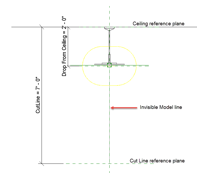 Figure 1: Light fixture elevation modifications[/caption]
This same technique can be used for electrical and data devices that are above the cut plane. If these devices are non-hosted, you can have the model line control by an elevation parameter within the family, which can raise the outlet, the model line, and output the height of the outlet to a tag.