We all know that there are two points used to help locate our projects - the Project Base Point and the Survey Point. Did you also know that there's a third, invisible point called the Revit Origin? The main difference between the first two points and the Revit Origin is that you cannot move/change the Revit Origin. When you start a new project, these three points are all on top of each other in the middle of your drawing area. Use reveal hidden elements to view them (the lightbulb in your view control bar), or turn them on here: V/G > Model Categories > Site.
If you have at some point moved the two visible points but want to find the Revit Origin, the best way is to use a linked CAD file. Create a CAD file with two lines marking the CAD Origin, and then link it in origin to origin.
So why is this origin important? Well, have you heard about the limitation in Revit of having objects modeled further than 20 miles away from the origin? The invisible Revit Origin is the important thing here because you can't change it, so it's imperative to make sure you know where it is.
You might be wondering, now what does this have to do with drafting patterns? Well, we know that drafting patterns cannot be moved or rotated, right? So how do they know how to line up with each other? Why, the Revit Origin, of course! When your objects with drafting patterns are far away from the origin (turns out it can be just 2 miles away and this happens) the graphics of the patterns start breaking down at different scales!
This will also cause problems with printing. The patterns do not print when you use vector processing, only when you use raster, and then they are very pixelated.
I set out to test this theory (above) and discovered some interesting things. This was all done in Revit 2017 with the latest service packs and updates installed. Here's my methodology.
I wanted to figure out at which distance away from the origin does the drafting pattern start breaking down. It only does it at the smaller scales (1/2” or 3” etc.)
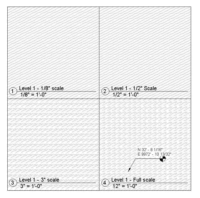
File 1:
- Drew a floor 10,000’ away from the origin.
- Made a crop region around it.
- Copied the view 4 times and set to 4 different scales (1/8, ½, 3”, 12”).
- Pattern broke down at the finer scales.
 Screenshot of File 1[/caption]
[caption id="attachment_29521" align="alignnone" width="700"]![]() File 1 printed using Vector Printing[/caption]
File 1 printed using Vector Printing[/caption]
[caption id="attachment_29520" align="alignnone" width="700"]![]() File 1 Printed using Raster Printing[/caption]
File 1 Printed using Raster Printing[/caption]
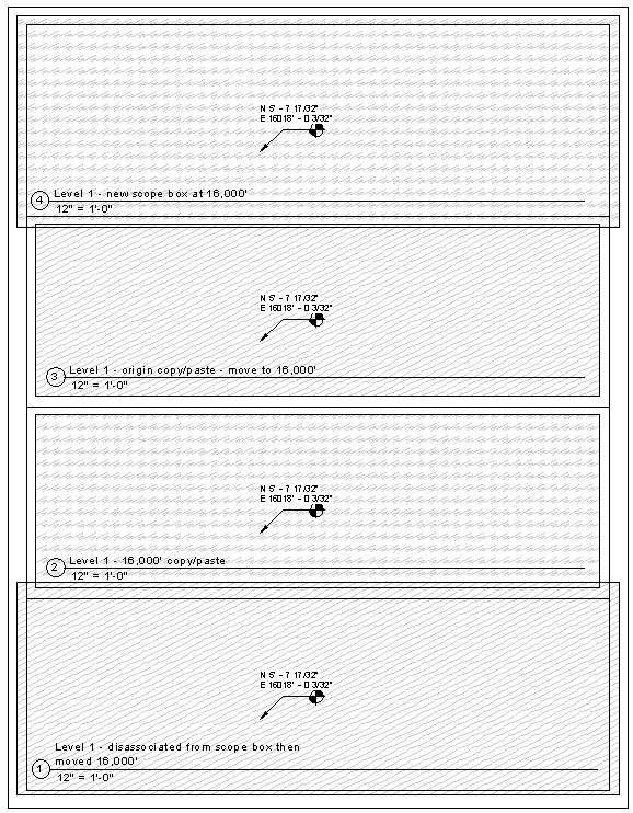
File 2: Test 1
I wanted to test how far away the pattern starts breaking down.
- Drew a floor with a drafting surface pattern at the origin.
- Created a crop region around it.
- Copied the floor 1000’ to the right.
- Duplicated the first view and then moved the crop region 1000’ to the left.
- I kept doing this, changing the distance until I had one that was 16,000’ away from the origin.
- In this file, the pattern never broke down, even at 16,000’ away.
- Created a new floor plan from scratch. Changed scale to 12”.
- Copied the crop boundary from the view at the origin.
- Pasted into the new plan view and moved it 16,000’ to the right.
- No breakdown!
- Created a new floor plan from scratch. Changed the scale to 12”.
- Copied the crop boundary from a view that was of a floor already at 16,000 ft.
- The pattern broke down!
 File 2 Screenshot[/caption]
[caption id="attachment_29523" align="alignnone" width="700"]![]() File 2 printed using Vector Printing[/caption]
File 2 printed using Vector Printing[/caption]
[caption id="attachment_29522" align="alignnone" width="700"]![]() File 2 printed using Raster Printing[/caption]
File 2 printed using Raster Printing[/caption]
So next, I tried tying the crop boundary to a scope box and then moving the scope box. In this scenario, the pattern does break down, even though I’m moving the crop region via the movement of the scope box. I disassociated the crop boundary from the scope box and then moved it and the pattern was fine.
To add to this fun, when I try to print to PDF using vector processing, none of the patterns print when the modeled elements are 16,000’ away from the origin. It only works when printing in raster (see image above).
So my conclusion from this is that somehow, the crop boundary stays tied to the origin. So if you move it, it’s okay, but if you make a new one, it isn’t. Unless it’s tied to a scope box.
The real conclusion here, though, is to make sure to always draw your modeled elements as close to the Revit Origin as possible. Otherwise, all sorts of weird things happen that you can't always replicate reliably!