I've been working recently on creating some light fixture families for a client. These families have some very specific requirements which required me to be creative with how I created the families.
Requirements:
- Face-hosted
- Embedded tagging information (utilizing custom shared parameters instead of the "Type Mark" parameter) and tagging information be in the same orientation for all instances (as much as possible)
- Embedded text for switching information
- Symbol that appears in plan needs to be the same size as the actual fixture, which required it to be a detail component instead of a generic annotation family.
Create your 3D family
The first step is to create the 3D family. I created hosted families with voids to cut the ceiling when placed in the model..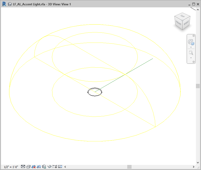
Create your 2D detail component family
Next create your detail component family. Make sure that it's parametric so that you can link the size parameters to the same parameters in the 3D family.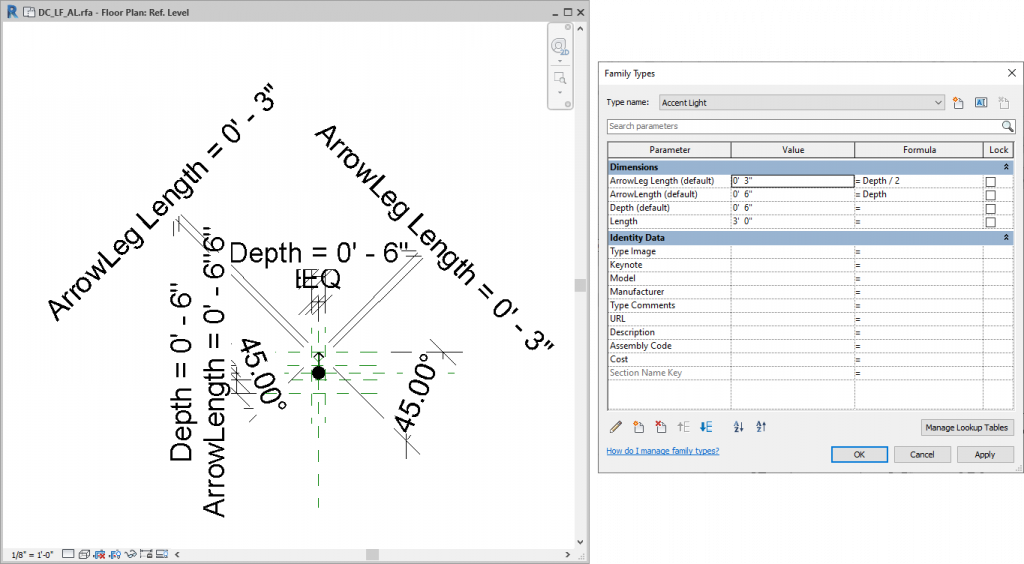
Putting it all together
- Load the detail component into the 3D family and align the center of it to the origin point in your 3D family.
- Draw a reference line (NOT reference plane) starting at the origin point of the family and out to an angle to the top right.
- Select the reference line and the two reference planes that create the origin, and isolate in the view. This step makes it easier to align and lock the reference line to the correct location.
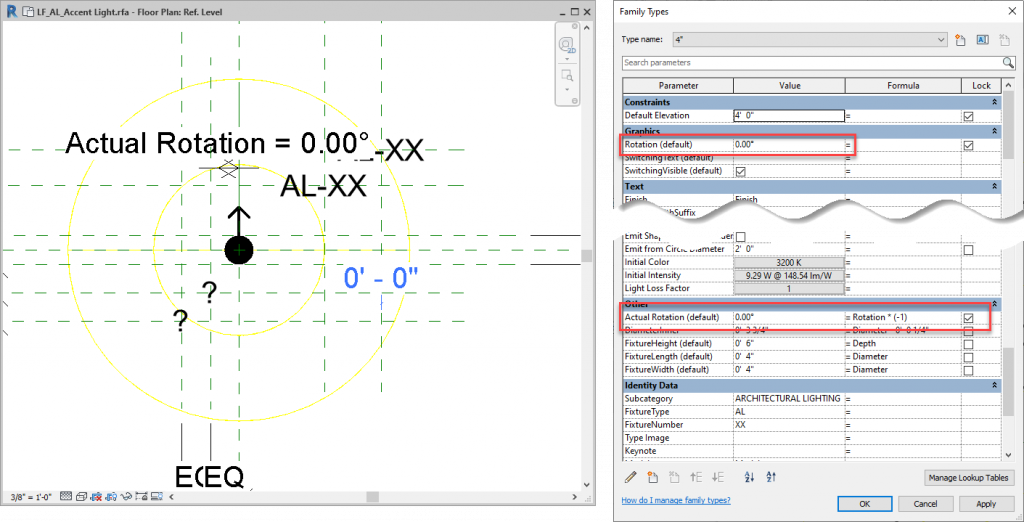
- If you are created a face-hosted family that will be in a ceiling, then you will need to create 2 parameters for the rotation because when you place the family in your project, it will be backwards, so you will need the second parameter to make it rotate clockwise in your view.
- Create a "Rotation" parameter as an angle type, put it under "graphics"
- Assign this parameter between the vertical reference plane and the reference line.
- Flex the family at all a bunch of angles between 0 and 360, to make sure that it's working properly.
- Reset your temporary hide/isolate settings.
- Click on the detail component, click "edit work plane" and assign t to the reference line.
- Flex the family again, to make sure it's working properly.
Hopefully this helps you all work with rotational parameters a little easier - they can be tricky!
Happy Reviteering!