Introduction
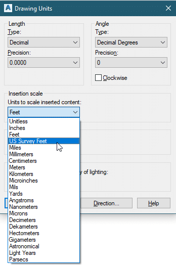
If you are using an AutoCAD-based product that is 2017 or later, you may have noticed that in your handy "Drawing Units" dialog, in the drop-down under "Insertion Scale," you now have two options for working in feet. They are "Feet," and "US Survey Feet."
It may be a big surprise to many people to find out that a "foot" could be anything other than what you've got on your tape measure or your Architect's Scale. But if you're a Surveyor or a Civil Engineer, this is something you've probably dealt with before. Here's a quick overview:
US Survey Feet vs. International Feet
The two types of "feet" that AutoCAD deals with are US Survey Feet and International Feet (A.K.A "Standard Feet" or simply "Feet.") "Why?!" you may ask. Well, the reasons stretch all the way back to the mid-1800s. Researching this is a fun history lesson, but in this blog, we are going to concentrate on how this affects us today.
First, let's understand the difference between the two types of "feet." The actual measured difference is very small, with one being derived as a decimal of a meter and the other being defined as an even fraction of meters:
- International Foot: 1 Foot = 0.3048 Meters
- US Survey Foot: 1 Foot = 1200/3937 meters (0.304800609601 Meters)
As you can see, the US Survey Foot is slightly bigger, although not by much. This means that there are less US Survey Feet per meter than there are International Feet per meter. The ratio between the two is literally 2/100,000 or 0.000002. So your next question may be "Why does this matter? It's so small!" Well, if you are dealing with small measurements, then it may not matter very much at all. But once you get into measurements over miles of road or pipe, and/or if you are working in State Plane coordinates whose values are often in the hundreds of thousands or even millions of feet, the conversion becomes pretty significant. Let's look at how this affects a 50-meter building.
- 50 meters = 164.0420 International Feet
- 50 meters = 164.0417 Survey Feet
So far, not too bad. The difference is only about 3 ten-thousandths of a foot, which is only about 4 thousandths of an inch and is negligible. But, let's take a look at something bigger, like the coordinates of a single sewer manhole in Virginia State Plane (South Zone) coordinates:
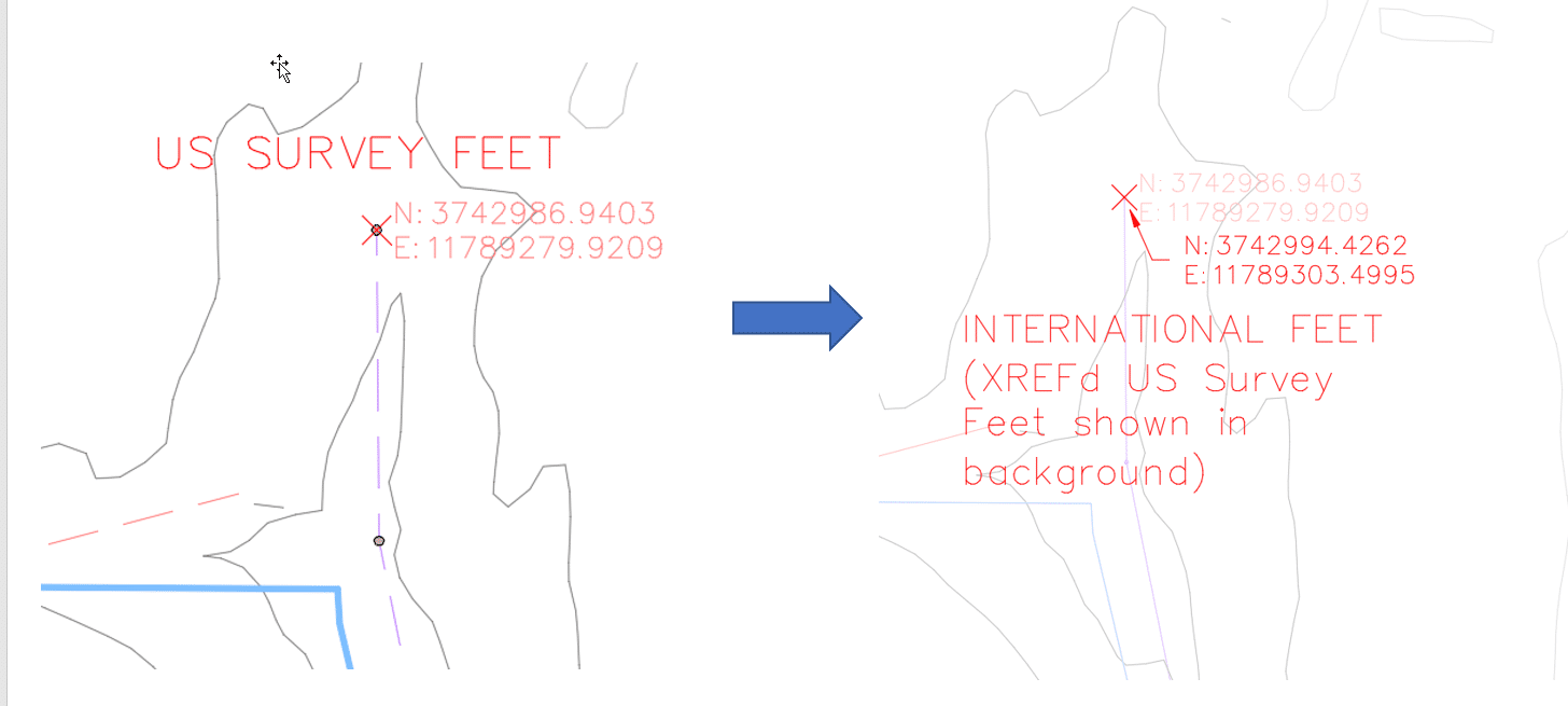
- International Feet: 11789303.4995, 3742994.4262
- US Survey Feet: 11789279.9209, 3742986.9403
Notice that the difference between these is more than 23 feet in the X direction and over 7 feet in the Y direction! That's a pretty big deal, right? The National Geodetic Survey has a great video that discusses the difference between International Feet and US Survey Feet, and why it is important to know which foot you are using. So if you want to understand this a little better, click here.
Autodesk Products
How Does this Affect AutoCAD Drawings in 2017 and Beyond?
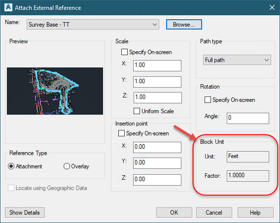
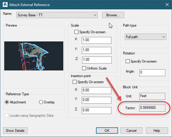
So what does this mean for AutoCAD users? Since AutoCAD now knows the difference between these two types of feet, it will convert one to the other during XREF and block insertion. If you have a drawing that is set to International Feet and you XREF it into a drawing that is set to "Feet," the program will perform a conversion calculation and the coordinates in the XREF file will be shifted in the current file. This shift is not something you will readily notice in the XREF or the Block Insert dialog prior to performing the conversion. You may think you're just fine because the insertion/XREF dialog shows a Scale Factor of 1, as shown below:
This is a product of the precision setting in your drawing being set too low to show the 0.000002 difference.
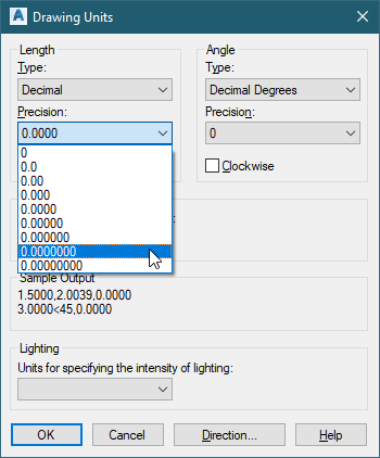
If you change the precision in your "Drawing Units" to show more decimals, as shown above, you will see the difference (illustrated below).
This can be extremely dangerous if you are dealing with drawings from AutoCAD 2016 or earlier since only the "Feet" option previously existed in the Units dialog. If you begin working in US Survey Feet now, then any legacy drawing you XREF or insert will come in shifted. With this knowledge, you may wonder why you would want to move to US Survey Feet at all. The answer comes if you or any of your contractors, partners, Surveyors, GIS Suppliers, etc., are working in State Plane Coordinates. Their coordinates will be in US Survey Feet and their drawings/files may very well be set that way. So if you are still working in Feet, then any attempt to insert this data could cause a shift that you may or may not even notice.
So what do I do with all those XREF Drawings I have?
We have established that working in US Survey Feet may be very necessary for professionals like Civil Engineers and Surveyors. But what does that mean for all of those legacy drawings that you have from previous versions that are set to "Feet" because they had no other option back then? Unfortunately, as mentioned above, the answer is that unless that setting is changed, a conversion calculation will be performed and they will come in shifted from the correct location. The only known workaround at this point is to create a folder of your necessary XREF drawings, open each one in AutoCAD 2017 or later, change their Units to "US Survey Feet," then save and close. Remember though, if you open and save these drawings in AutoCAD 2018 or later, the saved drawings will be in the new AutoCAD 2018 DWG format and will not be usable in previous versions without saving them back again.
What about Civil 3D?
For users of Civil 3D, the use of these two separate settings for "Feet" is an extremely important concept to understand. This is due to the fact that you are very often working in State Plane Coordinates in your drawing and/or your Survey Databases. It is important to note that establishing the "Drawing Settings" of a Civil 3D drawing and setting the coordinate system does not always automatically force the AutoCAD Units to be set to US Survey Feet, even though the units are clearly locked in on the "Units and Zone" tab of the "Drawing Settings" dialog, as shown below:
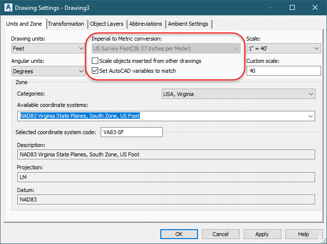
The key here is one of the check boxes that you see underneath of the "Imperial to Metric conversion" drop-down. If the "Set AutoCAD variables to match" box is checked, then setting the drawing to a coordinate system (ex. State Plane) that uses the US Survey Foot will automatically update the Insertion Units setting in the AutoCAD Units dialog to US Survey Feet. If this is not checked (which it is not by default in the Out-of-the-box templates), the Insertion Units in the AutoCAD Units dialog will not change, regardless of any of the selections made in this dialog.
Civil 3D Survey Databases and how they insert points into drawings will also be affected by this change. In Civil 3D 2016 and prior, if your Civil 3D Drawing settings were established as US Survey Feet and the drop-down in your AutoCAD Units dialog was set to "Feet," then points inserted to the drawing from a Survey Database that was also set to US Survey Foot would come in correctly. That is no longer the case in Civil 3D 2017 and beyond. The AutoCAD units MUST be set to US Survey Feet. Otherwise, the database will think that your drawing is in International Feet, a conversion will be performed during the insert, and the Points and Figures will come in in the wrong location.
Can't I just use "Unitless?"
To avoid this issue, I have heard of many users switching their AutoCAD units to "Unitless." Is this a good idea? Not really, for a variety of reasons. I discuss how the insertion of outside drawings such as Architectural buildings, details, blocks, etc. can be adversely affected by going with "Unitless" in a previous blog. For more information on this, see "Why can’t we all just get along?? – Helping Architects, Surveyors, and Engineers all play nice together in the AutoCAD sandbox."
Are Recap or Infraworks Affected?
Yes! Because Recap and Infraworks both understand State Plane and other coordinate types, the difference between US Survey Feet and International Feet can also have a large effect on how data is created, inserted into, or exported from these programs as well! This is another reason why working with your AutoCAD units set to "Unitless" is not recommended and why careful attention should always be paid to the type of "Foot" in use and the necessary Coordinate Systems.
What about Map 3D?
Based on my quick experimentation, it appears that inserting data from FDOs such as Shapefiles and SDF files are not affected by the difference between "Feet" and "US Survey Feet" in the AutoCAD Units dialog. Coordinate conversions performed by Map 3D are based on the Coordinate System set in the drawing by either the Map 3D or Civil 3D Drawing Settings.
Summary
Here are a few main points to keep in mind for working with US Survey Feet and International Feet in Autodesk products.
- Yes, there is a difference between the two.
- The difference is negligible for typical Architectural measurements but can be very large for projects that involve miles of work and/or State Plane coordinates.
- AutoCAD 2017 and beyond now see the Units setting of "Feet" as International Feet.
- This setting gets stored with a drawing and can be established in a standard template.
- The programs WILL perform a conversion calculation on the fly during many insertion commands if a difference is found in the units.
- If you are working in Map 3D 2017 or Civil 3D 2017 and beyond, there are multiple unit types that need to match or be set correctly (depending on the actual unit of the data)
- AutoCAD Drawing Units
- Map 3D Drawing Settings (Map 3D or Civil 3D Only)
- Civil 3D Drawing Settings (Civil 3D Only)
- Survey Database Settings (Civil 3D only)
As a refresher, listed below are the steps to access each of these settings:
- AutoCAD Drawing Units:
Application Menu -> "Drawing Utilities" -> Units. Or simply type "UNITS" at the command line and hit <ENTER> - Map 3D Drawing Coordinate System:
Map Setup tab (Map 3D or "Planning an Analysis" Workspace) -> "Coordinate System" panel -> "Assign" - Civil 3D Drawing Settings:
Settings tab of the Civil 3D Toolspace -> Right-click on the name of the drawing -> "Edit Drawing Settings" -> "Units and Zone" tab - Survey Database Settings:
Survey tab of the Civil 3D Toolspace -> Right-click on the name of the Survey Database -> "Edit Survey Database Settings" -> "Distance"
Good luck! And remember, Happy Units = Happy Sharing!!!